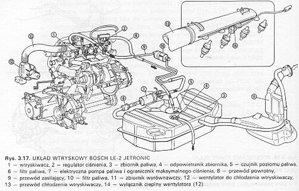
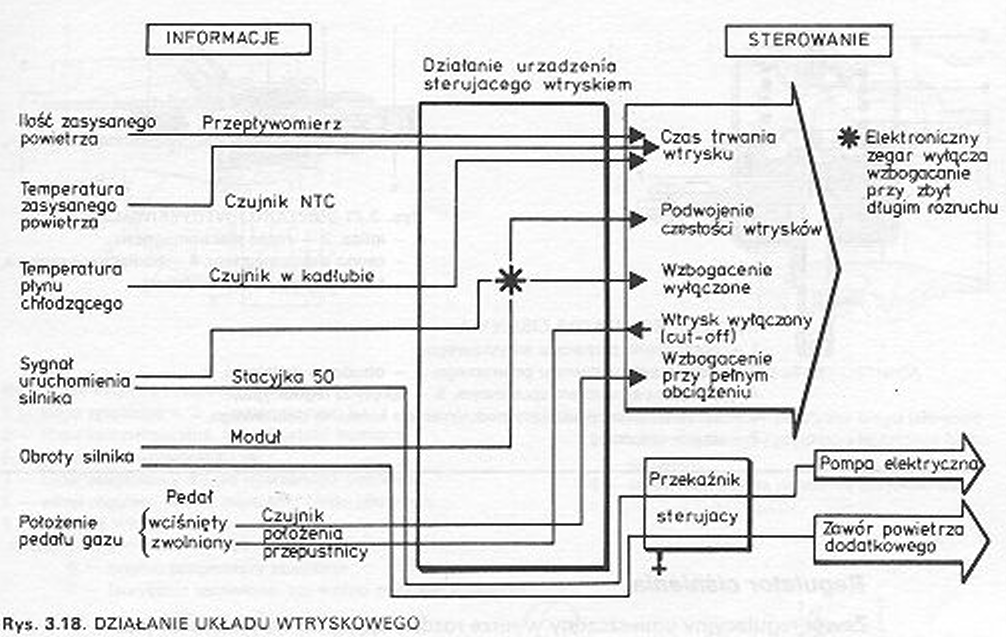
Engine 1300 The turbo is fueled by the Bosch LE-2 Jetronic electronic injection system. System components and the fuel flow path are shown in the figure 3.17. Whereas in the drawing 3.18 shows the relationship between the information and the resulting control functions. Fuel is fed from the tank through a roller-chamber pump to the injectors through the fuel filter. A regulating valve in the distributor pipe to the injectors limits the pressure to 3,0 barium (0,3 Mpa). The excess fuel is drained into the tank. The injectors are electromagnetically controlled and inject gasoline intermittently into the intake manifold. The same injectors deliver fuel during the engine start-up period, heating and normal operation.
The electric pump is of the roller-chamber type and its engine is flushed with gasoline. The pump starts running as soon as the engine is started, if its rotational speed is greater than 225 rpm. When the speed decreases, the pump is switched off.
Fuel filter
The fuel filter is located between the pump and the regulating valve. An arrow on the housing shows the direction of flow. The filter should be replaced every 40 000 km.
Pressure regulator
The control valve located in the distributing pipe to the injectors is of the diaphragm type. The vacuum in the intake manifold is used to control the fuel pressure supplied to the injectors.
Injectors
There is one injector in each cylinder. controlled by a built-in electromagnet.
Air flow meter
The flow meter measures the amount of air drawn in and gives the corresponding signal to the electronic control unit. This assembly has a bypass channel, through which unmeasured air can flow into the engine. By changing the amount of this air, the CO content in exhaust gas at idle speed is regulated.
Connection with a damper
The throttle located in the stub pipe is used to control the engine power. The idle speed is regulated by a screw placed in the bypass channel above the stub pipe. The damper must occupy a certain basic position, which is regulated by the screw constituting the lever stopper.
Auxiliary air valve
This valve supplies additional air to the engine during the warm-up phase.
Electric control system
The system supplies all elements with the required voltage, it processes sensor signals and controls the injectors in this way, that the correct fuel-air mixture is burned.
Coolant temperature sensor
The sensor is in contact with the coolant and changes its resistance depending on its temperature. This sensor is needed to control the starting phase and cold running of the engine.
Throttle position sensor
A sensor measures the throttle opening angle and transmits this information to the control device.
Control relay
The relay is activated electronically with the ignition switch and supplies it with the required current. This relay is equipped with a timer, which interrupts the supply of fuel immediately after the engine is stopped, for example, in the event of engine damage, the car overturned or the fuel line burst. This excludes the risk of fire.
Electronic control device
The device consists of two hybrid systems and is connected to the installation with a 25-pin connector. So that the injectors deliver the required amount of fuel under all engine operating conditions, the control device transforms the following input information:
– amount of air, air temperature,
– engine temperature,
– starter signal,
– engine speed,
– position of the "gas" pedal (idle / full "gas”)
– battery voltage.
Depending on the data, the device sends appropriate signals to the parallel connected injectors. Half of the amount of fuel needed to run the engine is injected for each revolution of the crankshaft. The device receives information about the start of injection from the primary winding of the ignition coil and processes the data in this way, so that for one work cycle there are two fuel injections. The control device limits the minimum and maximum pulse duration by continuously adjusting during real time, to control the following functions:
– enrichment during start-up,
– enrichment in the heating phase.
– enrichment during acceleration, enrichment at full load,
– cutting off the power supply during engine braking,
– flow rate regulation during engine braking.

