 Microplex ignition system by M. Marelli consists of a control device, the ignition distributor, module with an ignition coil and numerous sensors, that provide the information you need.
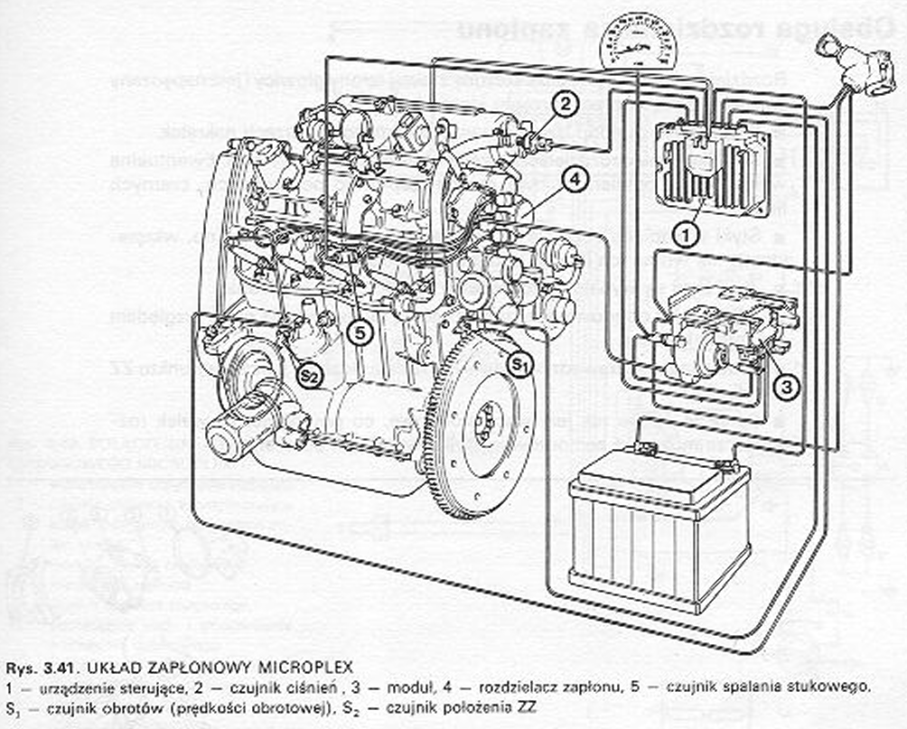
Contrary to conventional ignition, this system works without constant characteristics. Computing the ignition advance is done continuously on the basis of sensor data. The elements of the ignition system are shown in the figure 3.41.
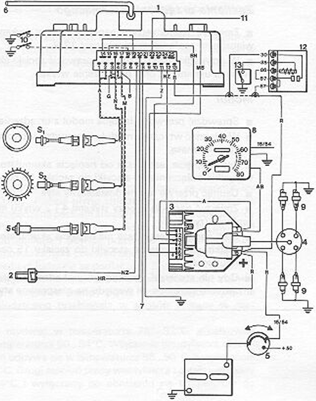
 Lynx. 3.43. MICROPLEX IGNITION CONNECTIONS
1 electronic control device
2 pressure sensor to protect against excessive boost pressure
3 – module with ignition coil A – ignition distributor
5 – knock sensor
6 – connection over- and vacuum from the intake manifold
7 Plug socket for engine diagnostics with Unitest
8 tachometer
9 – spark plugs
10 – switch or jumper with ground
11 – compressor operation indicator
12 - anti-burglary protection
13 – alarm sensor
The principle of operation of the system - see the diagram in the figure 3-43.
■ Sensor S2 provides information about the position of the piston at point ZZ based on the marks on the pulley.
■ Sensor S, at the flywheel determines the engine speed, as well as the angular position of the crankshaft.
■ Pressure sensor (2) oversees- and a vacuum in the intake manifold and provides the appropriate signal.
■ In the control device (1) The sensor signals are processed and the optimum ignition advance angle is determined.
■ Module (3) receives a signal at the right moment to open the primary circuit of the ignition coil.
■ At the same time, the module regulates the "fault angle" optimally” and keeps the energy in the primary winding constant. As a result, the ignition energy in the secondary winding is optimized and an undisturbed discharge is created.
■ Knock sensor in the cylinder head (5) tracks the possible formation of undesirable combustion in the engine. Burning it, also called motor ringing, is caused by uncontrolled ignitions.
■ If knocking occurs, this control delays ignition by 3C first.
■ When the knocking combustion continues, there is a further 3º delay, but not more than 15º in total
■ After a certain period of correct combustion, the ignition is shifted forward, to the limit of knocking combustion.
■ If the boost pressure exceeds the value 0,93 only (0.093 Mpa), the pressure sensor has grounded the safety switch on the module and the ignition is cut.