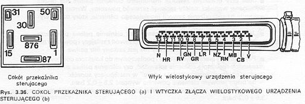
■ In the picture 3.36 the base of the control relay is shown, multi-pin connector of the control device and the position of the terminals.
■ Remove the connector plug from the control unit and connect the ohmmeter terminals to the following terminals:
– contact 1 and clamp 1 ignition coil.
– contact 2 and clamp 2 throttle position sensor,
– contact 3 and clamp 3 throttle position sensor,
– contact 4 and clamp 50 ignition switch,
– contact 5 and mass,
– contact 5 and clamp 5 air flow meter,
– contact 7 and clamp 7 air flow meter.
– contact 8 and clamp 8 air flow meter.
– contact 9 and clamp 9 air flow meter.
– contact 9 and clamp 9 throttle position sensor,
– contact 9 and clamp 18 additional air valve.
– contact10 and terminal 10 fluid temperature sensor,
– contact 12 and terminals of individual injectors,
– contact 13 and mass.
■ Eliminate interruptions in the lines and contacts.
■ The resistance of the injection units is measured with an ohmmeter with the component disconnected.
Required resistance values:
– additional air valve - 50 ± 10 Ω at 20 ° C measured across terminals,
– air flow meter – 350 ± 20 Ω between terminals 5 and 8;
200 ± 10 Ω at 20 ° C between terminals 8 and 9; 180 Ω at 60º C between terminals 8 and 9,
– fluid temperature sensor – 2…4 kΩ at 20ºC, 600…900 Ω w 50ºC,
100…300 Ω w 90°C,
– injector coil – 15…17 Ω w 20°C.
■ If different values are found, the assembly in question must be replaced.
■ For a quick and easier connection check, a Fiat diagnosis scanner can be used 1806034000.
Checking the throttle position sensor
With the throttle closed (resting on the bumper) there must be a transition between the contacts 18 and 2. There must be a transition between the contacts when the damper is fully open 18 and 3.
■ Throttle position sensor setting: loosen the sensor and turn it, to intercourse 18 and 2 the microswitch was closed during idling, however, it started switching on with the beginning of the throttle opening. Screw on the sensor in this position.
